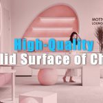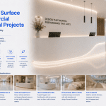
Acrylic solid surface is widely specified for healthcare interiors, hospitality bathrooms, commercial vanity systems, laboratory environments, and hygienic architectural applications. One common question from architects and project buyers is: Is acrylic solid surface waterproof?
The practical answer is yes in terms of moisture resistance—but with an important technical clarification. Acrylic solid surface is a non-porous engineered surfacing material, not a structural waterproof membrane.
This distinction matters when evaluating performance in wet environments.
Is Acrylic Solid Surface Waterproof?
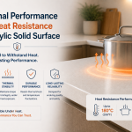
Acrylic solid surface offers excellent resistance to water penetration because the material is non-porous throughout its full thickness.
Unlike porous natural stone or wood-based decorative panels, moisture does not easily penetrate the material structure during normal use.
However, acrylic solid surface should not be confused with construction waterproofing systems such as roofing membranes or structural waterproof barriers.
In practical architectural applications, the correct description is:
- excellent moisture resistance
- non-porous surface performance
- high suitability for wet interior applications
Why Acrylic Solid Surface Resists Moisture
The performance advantage comes from the material’s homogeneous engineered structure.
Unlike layered decorative materials, acrylic solid surface is manufactured as a dense, non-porous surfacing material.
This delivers several practical benefits:
- reduced liquid absorption
- resistance to moisture penetration
- improved hygienic performance
- better resistance to staining from surface liquids
- reduced risk of hidden moisture damage
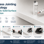
Why Seamless Fabrication Matters in Wet Areas
One of the biggest performance advantages of acrylic solid surface is seamless fabrication capability.
In many wet environments, moisture-related hygiene issues are not caused by the material itself—but by joints, seams, grout lines, or poorly sealed interfaces.
Acrylic solid surface helps reduce these risks because fabricated joints can be visually integrated and hygienically improved compared with many segmented surfacing systems.
This is especially valuable for:
- healthcare wash stations
- commercial vanity systems
- laboratory worktops
- hospitality bathrooms
- hygienic wall cladding systems
Solid Surface vs Other Materials in Wet Environments
| Material | Moisture Resistance | Seam Hygiene | Repairability |
|---|---|---|---|
| Acrylic Solid Surface | Excellent | Excellent | Excellent |
| Laminate | Surface resistant only | Edge vulnerability | Limited |
| Quartz | Excellent | Visible seams | Limited |
| Ceramic Tile | Good | Grout maintenance required | Low |
For hygienic wet-area architectural applications, acrylic solid surface offers a particularly strong balance of moisture resistance, seamless aesthetics, and maintainability.
Can Acrylic Solid Surface Be Used in Bathrooms?
Yes. Acrylic solid surface is widely used in bathroom and washroom applications.
Common applications include:
- integrated wash basins
- vanity tops
- shower feature walls
- commercial restroom counters
- hotel bathroom systems
Its moisture resistance and hygienic performance make it highly suitable for these environments.
Is Acrylic Solid Surface Mold Resistant?
Because acrylic solid surface is non-porous and easier to maintain hygienically, it helps reduce conditions that commonly support mold or bacterial buildup.
However, hygiene performance still depends on:
- proper cleaning
- correct fabrication
- joint quality
- overall installation design
No surfacing material should be marketed as “maintenance-free,” but acrylic solid surface performs exceptionally well in controlled hygienic environments.
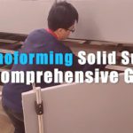
Fabrication Considerations for Wet Applications
Material performance in wet environments also depends on fabrication quality.
Key considerations include:
- proper joint preparation
- correct adhesive use
- sink integration quality
- edge detailing
- substrate compatibility
- correct installation design
Even excellent materials require professional fabrication to achieve expected long-term performance.
FAQ
Does acrylic solid surface absorb water?
Under normal use, acrylic solid surface demonstrates excellent resistance to water absorption due to its non-porous structure.
Is acrylic solid surface suitable for bathrooms?
Yes. It is widely used for vanity systems, integrated basins, wash stations, and hospitality bathroom applications.
Can mold grow on solid surface?
The non-porous nature of acrylic solid surface helps reduce mold-friendly moisture retention, especially compared with porous or joint-heavy systems.
Is solid surface better than laminate in wet areas?
For demanding wet-area commercial applications, acrylic solid surface generally offers superior long-term performance, hygiene, and repairability.
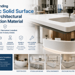
Talk to ACRION About Hygienic Architectural Solid Surface Solutions
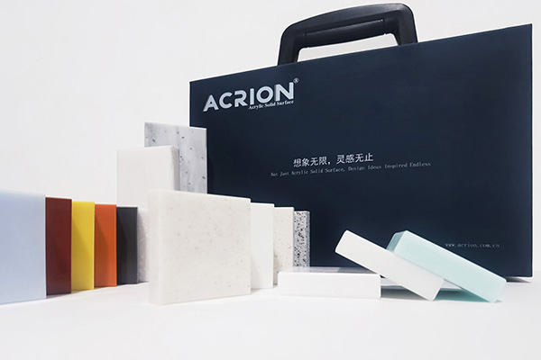
ACRION manufactures architectural-grade acrylic solid surface for healthcare, hospitality, laboratory, retail, and commercial interior applications worldwide.
If your project requires hygienic surfacing, wet-area design support, or technical specification consultation, our team is ready to assist.